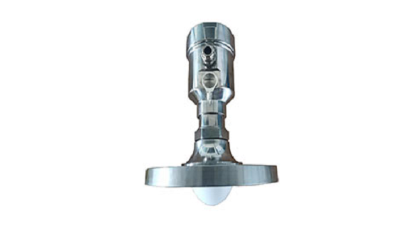

80G Radar Level Meter
The main benefits of using 78 GHz over devices using lower frequency are:
Based on the self-developed CMOS millimeter wave RF chip, a more compact RF architecture, a higher signal-to-noise ratio, and a smaller blind zone are realized.
5GHz working bandwidth means higher measurement resolution and accuracy.
3°antenna beam angle, so the interference in the environment has less impact on the instrument, and the installation is more convenient.
Shorter wavelength yields good reflection properties on sloped solids, so aiming towards material angle of repose is usually not necessary.
Support remote debugging and remote upgrading to reduce the cost of field personnel.
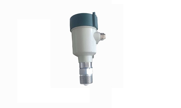
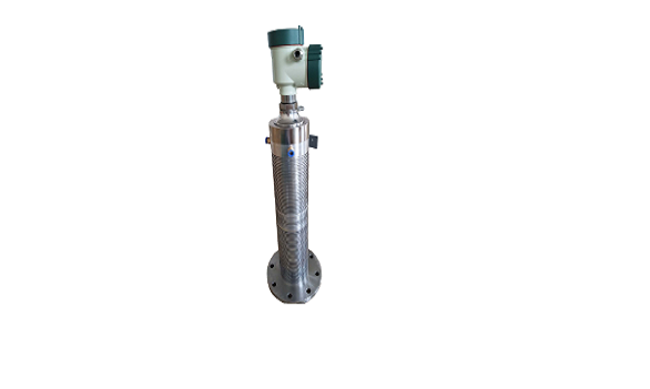
The series is FXRL radar operating at 76-81 GHz, which has a maximum measuring range of 120m and a minimum blind zone of 8cm. It supports 4-wire and 2-wire applications. Higher operating frequency and shorter wavelength make it ideal for solid applications, including those with extreme dust and high temperature to + 200℃. The radar consists of an electronic circuit coupled to a lens antenna and flange for quick and easy positioning.
TECHNICAL SPECIFICATION TABLE
| Frequency | 76GHz ~ 81GHz, 5GHz FMCW bandwidth |
| Measuring range | x0: 0.3 m ~ 60m x1: 0.08m~30m x2: 0.6m ~ 120m |
| Measurement accuracy | ±1mm |
| Beam angle | 3°/6° |
| Minimum measured dielectric constant | >=2 |
| Power | 15~28VDC |
| Communication | 2x: MODBUS 3x: HART/Series |
| Signal output | 2x: 4 ~ 20mA or RS-485 3x: 4~20mA |
| Fault output | 3.8mA, 4mA, 20mA, 21mA, hold |
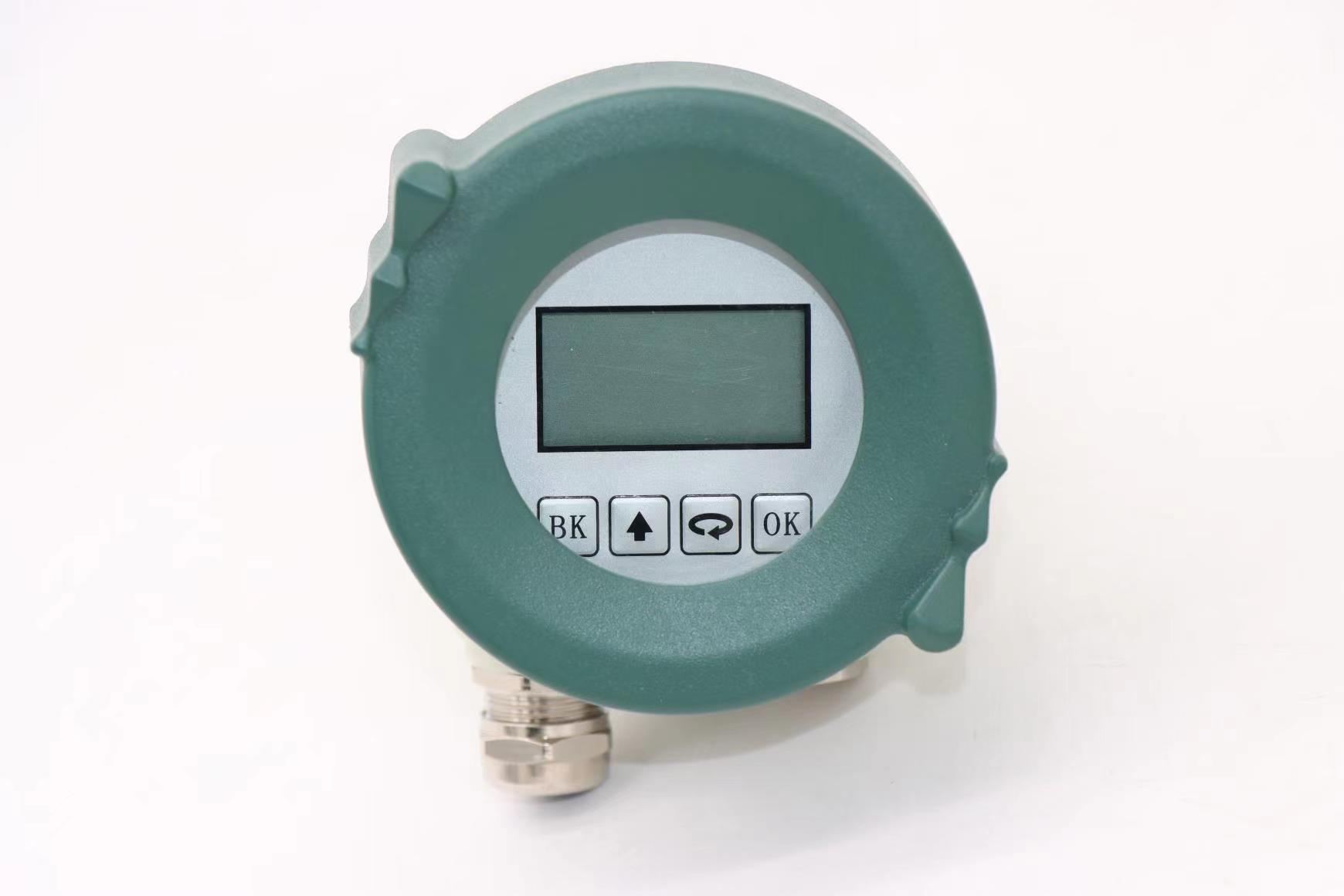
| Field operation / programming | 128 × 64 dot matrix display / 4 buttons PC software Bluetooth |
| humidity | ≤95%RH |
| Enclosure | Aluminum alloy, stainless steel |
| Antenna type | Lens antenna/anti-corrosive antenna / flange isolated by quartz |
| Process temperature | T0:-40~85℃; T1:-40~200℃; T2:-40~500℃; T3:-40~1000℃ |
| Process pressure | -0.1~2MPa |
| Product Size | Ø100*270mm |
| Cable entry | M20*1.5 |
| Recommended cables | AWG18 or 0.75mm² |
| Protection class | IP67 |
| Explosion-proof grade | ExdiaIICT6 |
| Installation method | Thread or flange |
| Weight | 2.480Kg/2.995Kg |
| Packing box size | 370*270*180mm |

Install
The main concern of installation is to aim to the material surface under test and on the other hand to avoid false echoes. Typical scenes are list below for correct installation.- Keep the antenna beam free of any interference such as ladders, pipes, steps, as shown in Fig.1.
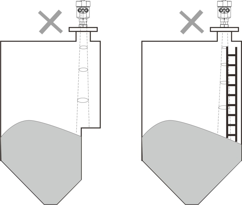
Fig.1 Example for avoiding false echo
- Avoid the contact between antenna beam and feeding flow, as shown in Fig.2.

Fig.2 Example for avoiding false echoes
- At least 200mm away from the wall for avoiding false echo.

Fig.3 Example for avoiding false echo
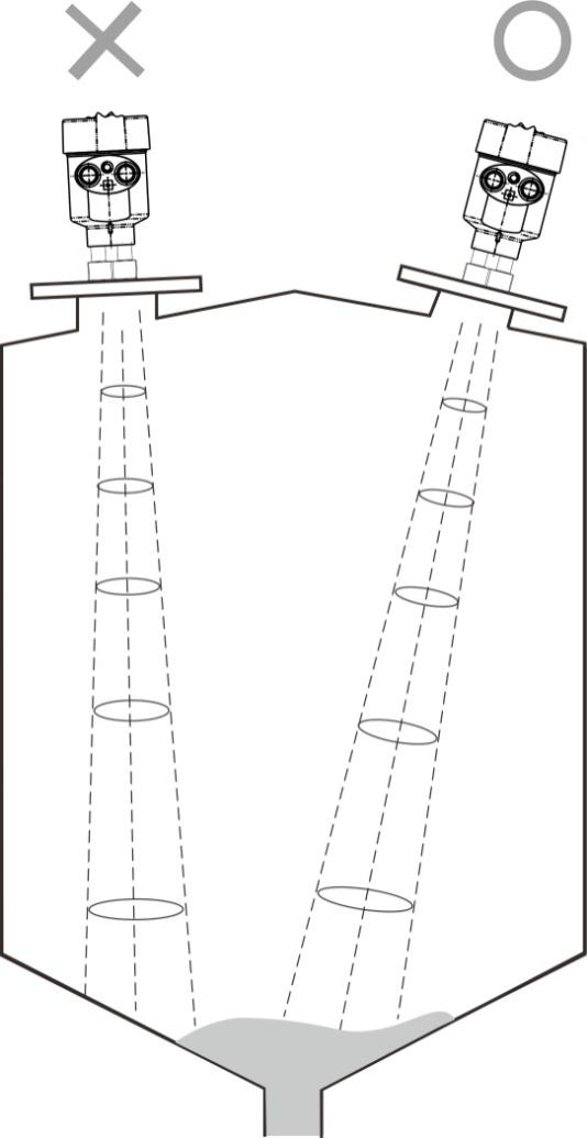
- Aiming the antenna beam to the bottom of tapered vessel for avoiding false echo when the level is at the bottom of the tapered vessel.
